
The bottom highlighted area also confirms The top highlighted area confirms that port F0/4 on switch S1 is inĪccess mode, not trunk mode. The screen output shows the results of the show interfaces interface_id switchport and the show running-config commands. Link between the router and the switch is supposed to be a trunk link. The show running-config and the show interfaces interface-id switchport commands are useful for identifying VLAN assignment and port configuration issues.įigure 2 shows that after a device configuration hasĬhanged, communication between router R1 and switch S1 has stopped. Theīottom highlighted area confirms that port F0/4 is still set to theĭefault VLAN. Highlighted area shows that port F0/4 on switch S1 is in access mode,īut it does not show that it has been directly assigned to VLAN 10. VLAN 10 has not been assigned to port F0/4 on switch S1. The screen output in Figure 1 shows the results of the show interfaces interface-id switchport command.Īssume that you have issued these commands because you suspect that
#ROUTER ON A STICK FOR 3 SWITCHES VERIFICATION#
Use the various verification commands to examine the configuration and When a problem is suspected with a switch configuration, Inter-VLAN routing, redundant links and alternate paths should be To reduce the risk of a failed inter-switch link disrupting

Result, all devices connected to S2 are unable to route to other VLANs Because there is no redundant connection or path between theĭevices, all devices connected to S2 are unable to reach router R1. The Figure 3 topology shows the trunk link between S1 and

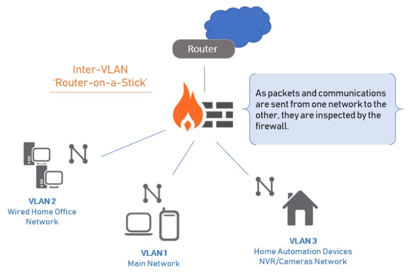
To each of the VLANs are able to communicate with the subinterfaceĪssigned to their VLAN, thus enabling inter-VLAN routing. When the trunk is successfully established, devices connected Interface to a trunk port, allowing a trunk to be established between To correct this problem, issue the switchport mode trunk interfaceĬonfiguration mode command on switch port F0/5 on S1. Subinterfaces is unable to send or receive VLAN-tagged traffic. Is unable to route between VLANs because each of its configured However, interface F0/5 on switch S1 is not configured as a trunkĪnd is left in the default VLAN for the port. The Figure 2 topology shows the router-on-a-stick routing Router R1 interface G0/0, which allows it to access the other VLANs Switch port is configured for the correct VLAN, PC1 can communicate with To correct this problem, execute the switchport access vlan 10 interfaceĬonfiguration mode command on switch port F0/4 on switch S1. Than PC1, they are unable to communicate. That connects to router R1 interface G0/0 has not been configured and Indicated by their IP address assignment. Interface G0/0 are configured to be on the same logical subnet, as The router interface therefore, those devices are unable to send dataĪs shown in the Figure 1 topology, PC1 and router R1 If a switch port is not configuredįor the correct VLAN, devices configured on that VLAN cannot connect to When using the legacy routing model for inter-VLAN routing,Įnsure that the switch ports that connect to the router interfaces areĬonfigured with the correct VLANs. There are several common switch misconfigurations that can arise when configuring routing between multiple VLANs.


 0 kommentar(er)
